-
Highlight
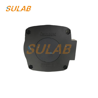
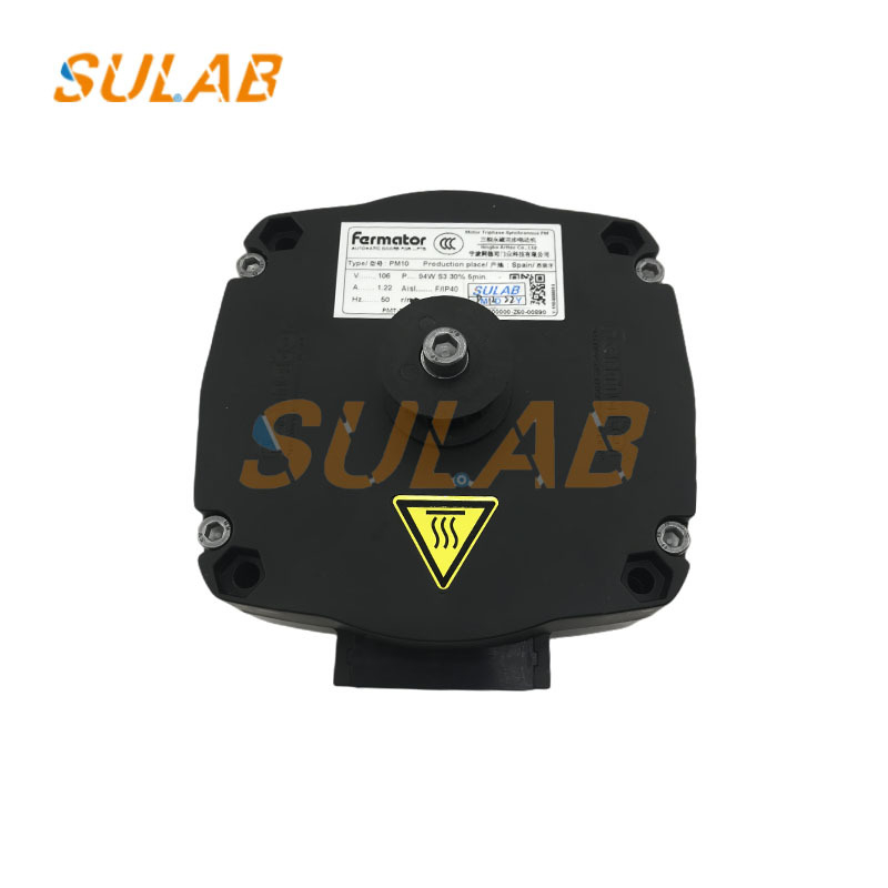
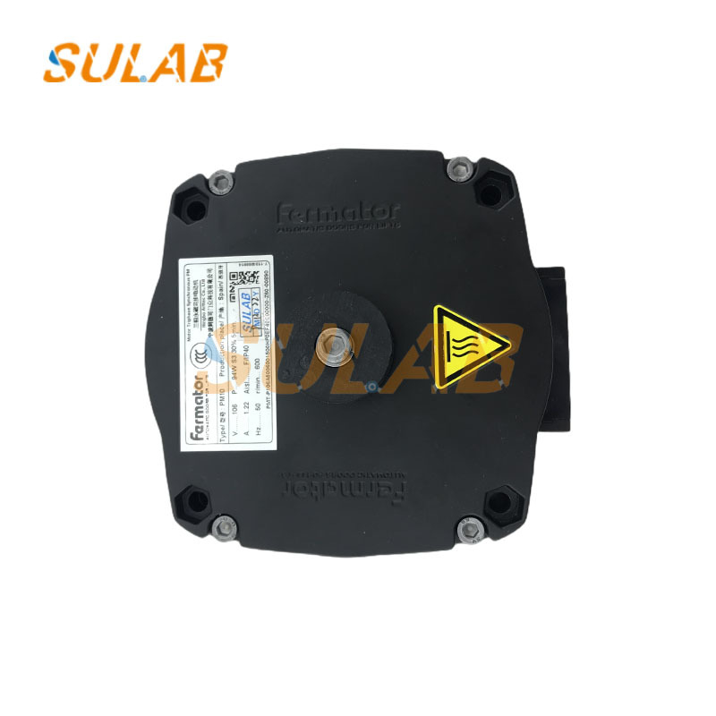
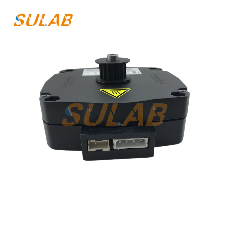
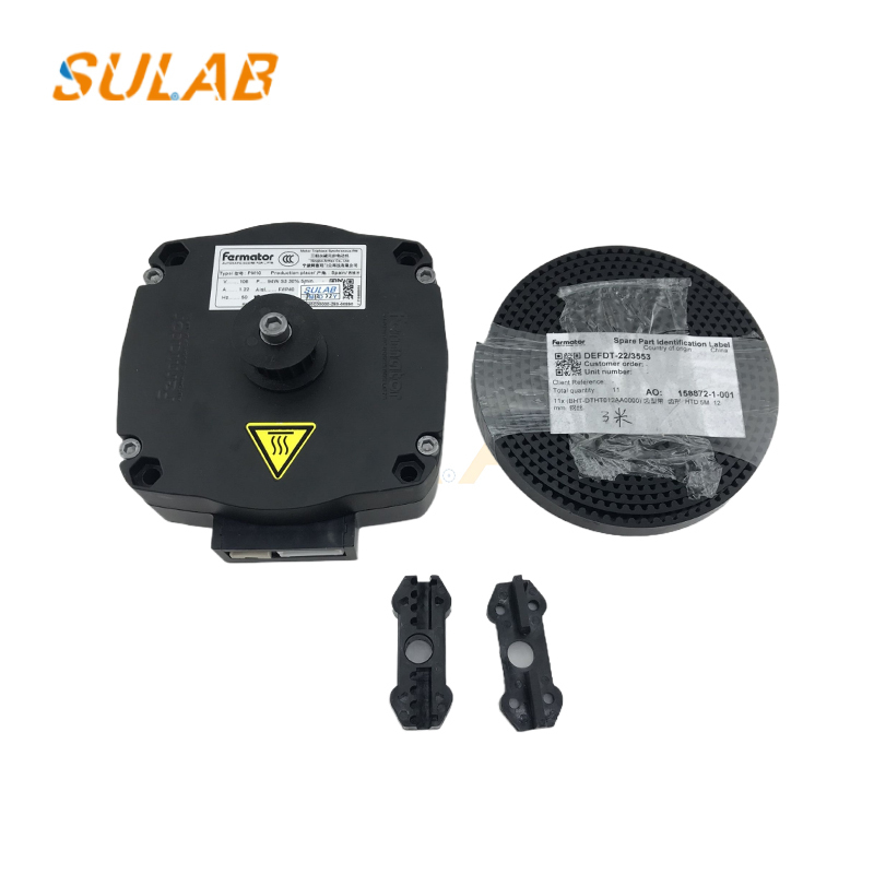
24V DC elevator door motor
,permanent magnet elevator motor
,SULAB PM10 elevator motor
-
BrandSULAB
-
DescriptionElevator Parts
-
ModelPM10
-
MOQ1PC
-
TransportionTNT, UPS, DHL, Fedex, Air, Sea
-
ApplicableElevator
-
PackagesCarton, Wooden Case, Pallet Etc
-
Delivery TimeNormally 2-3 Working Days After Payment
-
WarrantyOne Year
-
Payment MethodCompany Bank, Western Union, Alibaba, Paypal Etc
-
Brand NameSULAB
-
Model NumberPM10
-
Minimum Order Quantity1PC
-
Delivery TimeNormally 2-3 working days after payment
-
Payment TermsD/A,L/C,D/P,T/T,Western Union,MoneyGram
SULAB PM10 Elevator Door Motor 24V DC Permanent Magnet


Elevator Accessories Elevator Door Motor VF4+VF5+ PM10 PMVC Universal AC Motor Motor Inverter PM10
PM10 Permanent Magnet DC Motor (PMDC Motor): "Electrified coils rotate in a magnetic field."
This type of PM10 motor (such as the Parvalux PM10 series) is the most common. Its operating principle is based on Ampere's law (a current-carrying conductor in a magnetic field experiences a force perpendicular to the current and magnetic field). The specific process is as follows:
Establishing a fixed magnetic field
The stator (the stationary part) of the motor contains internal permanent magnets (such as arc-shaped permanent steel magnets), which create a fixed-direction "main magnetic field" (for example, with the north pole at the top of the stator and the south pole at the bottom, with the magnetic field pointing from north to south).
Electrified rotor coils experience forces
The motor rotor (the rotating part) is an armature wound with multiple coils. The coils are connected to an external DC power supply via a "commutator" (a cylindrical component made of multiple copper plates) and "brushes" (stationary conductive carbon brushes that slide in contact with the commutator). When DC current flows through the brushes into the rotor coils, they experience an Ampere force within the stator's fixed magnetic field. The direction of this force is determined by the "left-hand rule": palm facing the north pole of the magnetic field, fingers pointing in the direction of the current, and thumb pointing in the direction of the force. Because the rotor coils are arranged in a circular pattern, the forces acting on coils at different locations differ in direction, ultimately creating a "rotational torque" that drives the rotor.
| Brand | SULAB |
| Description | Elevator parts |
| Model | PM10 |
| MOQ | 1PC |
| Transportion | TNT, UPS, DHL, Fedex, Air, Sea |
| Applicable | Elevator |
| Packages | Carton, Wooden case, Pallet etc |
| Delivery Time | Normally 2-3 working days after payment |
| Warranty | One year |
| Payment Method | Company Bank, Western union, alibaba, Paypal etc |
Stator and Rotor Structure
The stator consists of multiple magnetic poles with coils (e.g., 4-pole or 8-pole). The coils are grouped according to a "phase sequence" (commonly 2-phase or 4-phase). When energized, each set of coils generates a magnetic field, causing the stator's magnetic poles to assume a north or south pole.
The rotor contains built-in permanent magnets, forming fixed magnetic poles (e.g., a cylindrical rotor has multiple north and south poles evenly distributed across its surface; for example, a 10-pole rotor has five pairs of north/south poles). Pulse signals drive the stator magnetic field switching. An external controller (such as a PLC or stepper motor driver) sends pulse signals to the stator coils, energizing the stator coils of different phases in a specific sequence. For example, in a two-phase permanent magnet stepper motor, when the "Phase A" coil is energized, the stator's A-phase magnetic pole generates a north pole. The rotor's south pole is attracted to the A-phase north pole, and the rotor rotates until the rotor's south pole is aligned with the stator's A-phase north pole (step one).
Then, when Phase A is disconnected and Phase B is connected, the stator's B-phase magnetic pole generates a north pole, and the rotor's south pole turns toward the B-phase north pole (step two).
Then, when Phase B is disconnected and Phase A is connected (reverse phase A) (the current in the A-phase coil is reversed, and the magnetic pole becomes south). The rotor's south pole is attracted to the reversed north pole of Phase A (actually the original A-phase coil's north pole reversed), and rotation continues (step three).
The cycle repeats: "Phase B reverse → Phase A → Phase B → ..." In the cycle, the stator magnetic field switches periodically, and the rotor rotates in steps as the magnetic field switches.
Our products are sold all over the world, you can rest assured.