
OTIS Elevator GECB-AP Main PCB Board DCA26800AY5 DDA26800AY5 With ABA26800AVP6
-
Highlight
GECB AP Main PCB Board
,Main PCB Board DCA26800AY5
,main circuit board DDA26800AY5
-
Product NamePCB Board DCA26800AY5 DDA26800AY5 With ABA26800AVP6
-
Model NumberDCA26800AY5 DDA26800AY5 With ABA26800AVP6
-
Delivery Time2-3 Working Days
-
Supply Ability1000pcs Per Month
-
After-Sale ServiceOnline Technical Support
-
Suitable ForElevator
-
WarrantyOne Year
-
TypeElevator Parts
-
MOQ1PC
-
TransportionTNT, UPS, DHL, Fedex, Air, Sea
-
ApplicableElevator
-
PackagesCarton, Wooden Case, Pallet Etc
-
Delivery TimeNormally 2-3 Working Days After Payment
-
Payment MethodCompany Bank, Western Union, Alibaba, Paypal Etc
-
BrandSulab
-
DescriptionElevator Parts
-
ModelFB-9B
-
Brand NameOT
-
Model NumberDCA26800AY5 DDA26800AY5 With ABA26800AVP6
-
Minimum Order Quantity1
-
Packaging DetailsCarton
-
Delivery Time2-3 working days
-
Payment TermsCompany Bank, Western union, alibaba, Paypal etc
-
Supply Ability1000pcs per month
OTIS Elevator GECB-AP Main PCB Board DCA26800AY5 DDA26800AY5 With ABA26800AVP6
Details for OTIS Elevator GECB-AP Main Pcb Board DCA26800AY5 DDA26800AY5 With ABA26800AVP6
| Brand | OT |
| Description | Elevator Circuit PCB Board |
| Part No. | DDA26800AY5 With ABA26800AVP6 |
| MOQ | 1PC |
| Transportion | TNT, UPS, DHL, Fedex, Air, Sea |
| Applicable | Elevator |
| Packages | Carton, Wooden case, Pallet etc |
| Delivery Time | Normally 2-3 working days after payment |
| Warranty | One year |
| Payment Method | Company Bank, Western union, alibaba, Paypal, Personal bank etc |
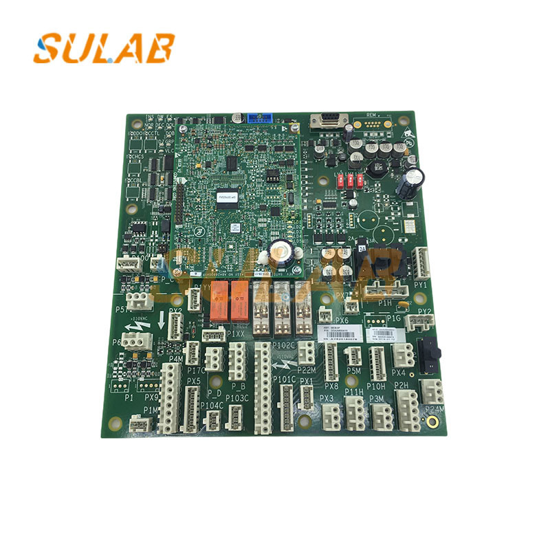
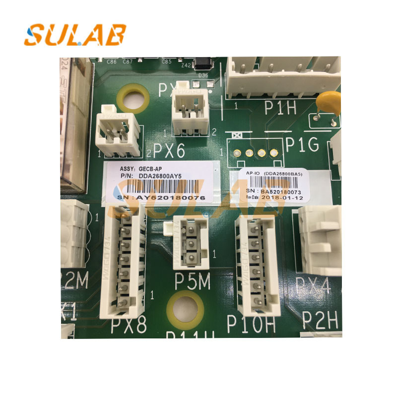
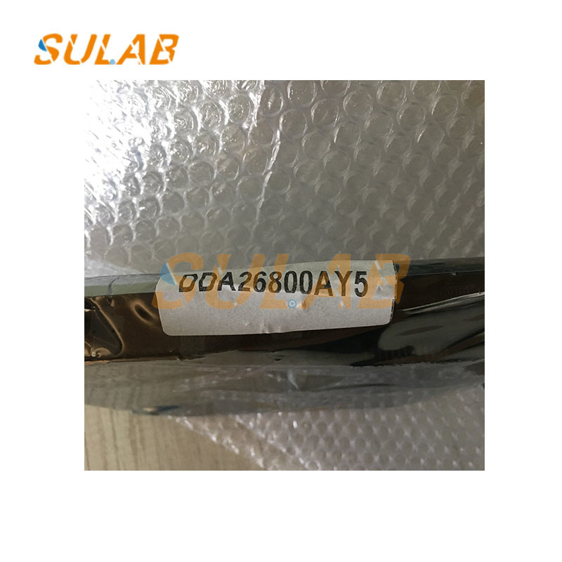
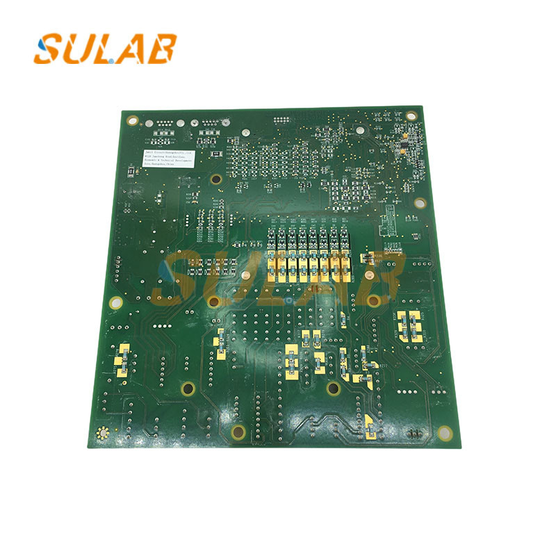
Pictures for OTIS Elevator GECB-AP Main Pcb Board DCA26800AY5 DDA26800AY5 With ABA26800AVP6
![]()
Inspection mode GECB power-on inspection
Voltage check
Disconnect the main power supply in the distribution box, the car and shaft lighting power switches, and all air switches in the control cabinet, unplug the GECB and all plug-ins on the inverter, and then turn the operating mode knob on the emergency electric running box to EROR mode. Use the electricity meter to confirm that the voltage range of each phase in the distribution box should be 380V±5%, and turn on the main power switch of the distribution box.
Use an electric meter to confirm the initial side voltage range of the lighting power switch is 220V±5%, and close the switch.
Turn on the main power switch and observe whether the indicator light of the inverter is on.
Close CP1 and observe whether the phase sequence relay is normal.
Confirm that the initial side voltage of each air switch is normal according to the table below, then close the switch.
Our products are sold all over the world, you can rest assured.