-
Highlight
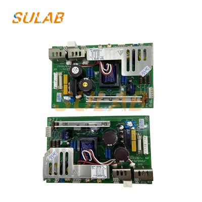
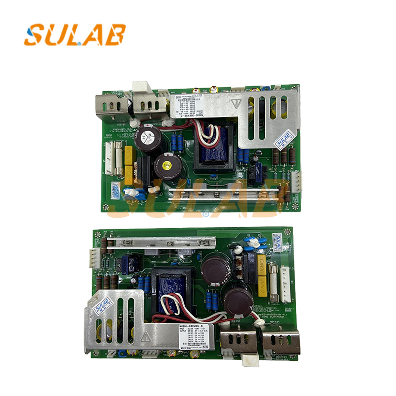
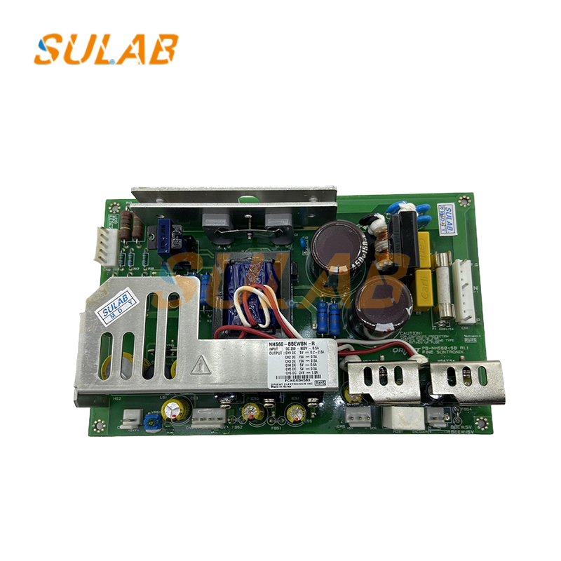
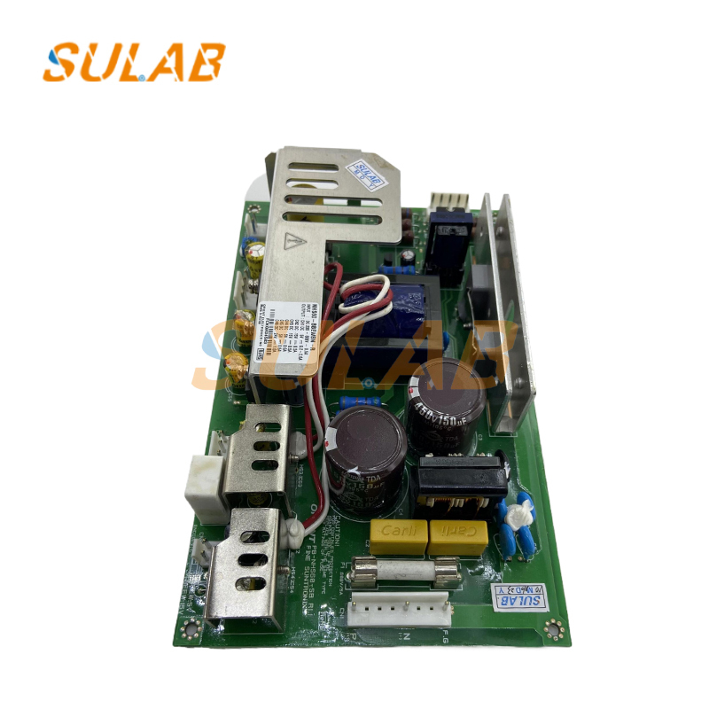
modern elevator inverter power board
,elevator control board PB-NHS60-SB
,elevator PCB board with warranty
-
BrandSULAB
-
DescriptionElevator Parts
-
ModelPB-NHS60-SB NHS60-BBEWBN-R
-
MOQ1PC
-
TransportionTNT, UPS, DHL, Fedex, Air, Sea
-
ApplicableElevator
-
PackagesCarton, Wooden Case, Pallet Etc
-
Delivery TimeNormally 2-3 Working Days After Payment
-
WarrantyOne Year
-
Payment MethodCompany Bank, Western Union, Alibaba, Paypal Etc
-
Brand NameSULAB
-
Model NumberPB-NHS60-SB NHS60-BBEWBN-R
-
Minimum Order Quantity1PC
-
Delivery TimeNormally 2-3 working days after payment
-
Payment TermsL/C,D/A,D/P,T/T,Western Union,MoneyGram
SULAB Elevator Power Board PB-NHS60-SB NHS60-BBEWBN-R 60°C Max
Modern elevator inverter power board is suitable for modern elevator original modern elevator control board PB-NHS60-SB NHS60-BBEWBN-R
Core Component Inspection and Replacement
Capacitors: Inspect the electrolytic capacitors on the power board (especially the high-voltage filter capacitors). If any capacitance decreases (measured with a capacitance meter, the capacitance is less than 80% of the nominal value), leaks, or bulges, immediately replace them with capacitors of the same specifications (voltage, capacitance, and temperature rating). (We recommend Taiwanese or Japanese brands, such as Teapo and Nichicon, to prevent re-damage to inferior capacitors in a short period of time.)
Power Chip/Module: Use an infrared thermometer to measure the temperature of the power chip (such as the LM1117 or UC3842). Under full load, the temperature should be ≤60°C. If the temperature is too high (over 70°C), check the heat sink for proper fit (reapply thermal grease) or determine if the chip is deteriorating and needs replacement.
Fuse/Resistor: Verify that the fuse (or resistor) on the power input side is not blown. If so, first check for a short circuit (such as an internal short in the power board or excessive load). After correcting the problem, replace the fuse with one of the same specifications. (Do not replace it with a wire to avoid fire.)
| Brand | SULAB |
| Description | Elevator parts |
| Model | PB-NHS60-SB NHS60-BBEWBN-R |
| MOQ | 1PC |
| Transportion | TNT, UPS, DHL, Fedex, Air, Sea |
| Applicable | Elevator |
| Packages | Carton, Wooden case, Pallet etc |
| Delivery Time | Normally 2-3 working days after payment |
| Warranty | One year |
| Payment Method | Company Bank, Western union, alibaba, Paypal etc |
Maintenance Precautions
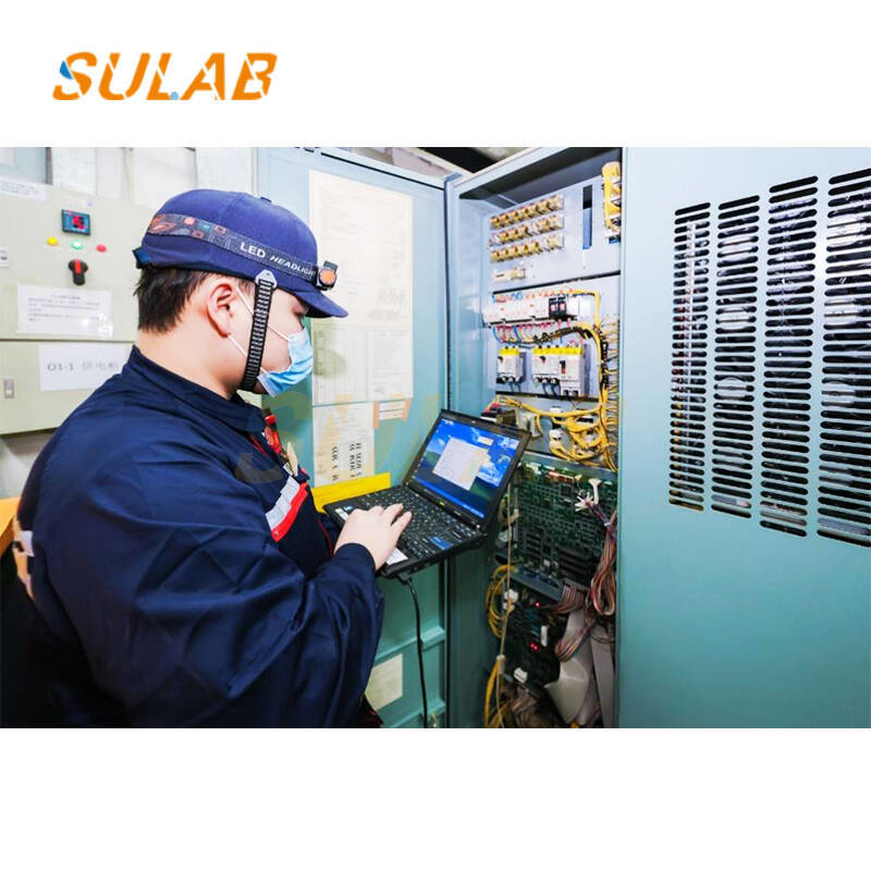
All maintenance operations must be performed after the elevator is powered off (disconnecting the main power supply to the machine room). A "Maintenance in Progress, Do Not Close" warning sign must be displayed to prevent electric shock accidents.
When removing the power board, first record the wiring sequence of the terminals (take photos or draw a diagram) to avoid wiring errors during reassembly. Small parts such as screws and terminals should be stored separately to prevent loss.
When powering on after maintenance, first test with no load (disconnect the load and test only the power board output voltage). After confirming that the voltage is normal, connect the load to avoid component damage due to wiring errors when powering on with load.
Create a maintenance file that records the date, content, test data (such as voltage and capacitance), and component model numbers of each maintenance operation to facilitate tracing the cause of the problem and predicting the next maintenance interval.
